Thursday, November 20, 2025

Rooms vs. Spaces in Revit: Why Something So Simple Gets Complicated

In Revit, Architectural models use Rooms (blue), while Engineering models use Spaces (green). Rooms serve as placeholders for architectural information; Spaces host data needed by engineering systems. On paper, that sounds straightforward. In practice? It can get surprisingly messy—especially when all you want to do is tag the rooms… er, spaces.

Tagging 101

In an Architectural model, you tag Rooms with room tags to display the room name, number, and other properties.
When that architectural model is linked into an engineering model, engineers tag Spaces with space tags to show the same name and number information.

This creates the first big point of confusion:

Two different objects need to display the same name and number.
One comes from Architecture.
One comes from Engineering.
Both appear on drawings.
They need to match.

There are several ways to accomplish this—each with its own limitations.


Option 1: The Autodesk Space Naming Utility (SNU)

Autodesk provides the Space Naming Utility (SNU), which copies the Room Name and Room Number from the architecture’s Rooms into the engineer’s Spaces.

Simple, fast, reliable… mostly.

But SNU breaks down in edge cases.
For example, imagine a single large Room divided by Space Separation Lines. This creates multiple Spaces inside one Room. Each Space wants the same Room Name and Number—but Revit doesn’t allow duplicate Space Numbers.

So Revit appends a suffix like:

  • Space 101

  • Space 101-1

  • Space 101-2

…and so on.

This can quickly become unmanageable, especially on large projects.


Option 2: Tag Spaces with the Room’s Information

Another approach is to customize the Space Tag so that it reads and displays the Room’s Name and Number instead of the Space’s own parameters.

This offers multiple advantages:

  • Engineers can still store their engineering-specific Space properties (for tools like Trace or HAP).

  • Tags stay visually consistent with architectural room names/numbers.

  • No need to rely on SNU’s copying logic.

A related variation is tagging linked Rooms directly using a Room Tag in the engineering model. In some cases, this even eliminates the need to place Space objects entirely.

That said, I don’t recommend skipping Spaces, because the engineering benefits (flows, loads, calculations, schedules) overwhelmingly outweigh the few extra steps needed for setup.


The Phasing Curveball

Rooms and Spaces don’t behave like most Revit objects when phasing is involved.
They do not persist across phases.

If a room spans three phases with no physical change—existing, demo, new—you still need to:

  • Create a separate Room in each phase

  • Tag it in each phase

  • Make sure the name/number stays identical manually

Then you must replicate that process for Spaces using whichever tagging strategy you adopted earlier.

And if one phase changes? You’re back to updating all copies, in both Rooms and Spaces.
This is one of Revit’s longer-standing headaches.


Linking, Interlinking, and the “Broken Room Bounding” Problem

On many real projects, architects send multiple Revit models:

  • Interior & Exterior

  • Shell & Core + Interior Fit-Out

  • Separate discipline models

  • Or various other combinations

Because these files come from outside the engineer’s network, their links arrive broken.

This is where things get risky.

If the links aren’t re-assembled correctly:

  • Rooms may not form in the linked architectural model.

  • Without Rooms, the MEP Spaces cannot detect their associated Rooms.

  • Then SNU, room-tagging, and space-tagging strategies all fail.

  • Engineering tags will show blank or incorrect data.

It snowballs fast.

Bottom line:
When an architectural model arrives from outside, all its links must be reconnected immediately.
Otherwise, Room/Space coordination is dead on arrival.


Closing Thoughts

Rooms and Spaces are foundational to coordination between architecture and engineering in Revit. But because they have different behaviors, don’t persist across phases, and depend heavily on correct linking, they can easily turn into a source of frustration.

With the right tagging strategy and disciplined file management, you can avoid most pitfalls—and ensure both models speak the same language.

Saturday, November 15, 2025

It's been a wild ride. Now it's time to get back in business.

Working at CASE was an amazing experience. The collection of talent they brought together was unlike anything I’ve ever seen—truly next-level thinkers, builders, and innovators. I’ve always liked to drink from the fountain of knowledge, but that team was a fire hose. I’m grateful for every bit of guidance, inspiration, and camaraderie they offered.

Then came the buyout. One of CASE’s clients decided they wanted all that talent under their roof, and in many ways it made sense. But three years later, that once-in-a-lifetime team is now scattered to the four corners. I wish I could say we’ve all stayed tightly connected, but like so many things, the day-to-day hustle and distance took their toll.

In the decade since, I’ve been working as a Technology Manager for Consulting Engineers, supporting multidisciplinary teams, developing digital tools, and helping firms bridge the gap between design intent and practical implementation. It’s been a rewarding stretch—hands-on, fast-moving, and a front-row seat to how tech reshapes AEC workflows.

Now I’m circling back to some old interests. After far too long away from writing, it’s time to start again. I have a lot in the pipeline—thoughts, tools, and experiments I’m finally ready to share. I’m also deep into a new Revit Add-In that I’ll be unveiling soon.

If you’ve stuck around this long, thanks for being here. More to come.

Tuesday, December 29, 2015

Room Separation Lines Don't Play Well with Others

Please Use Sparingly

Room Separation lines are a necessary eval from an MEP perspective. There are times they must be used, and from an architectural perspective are completely appropriate.  Here is the rub, they don't just divide rooms, they also divide spaces. Spaces are used by MEP in place of rooms as they have more parameters pertinent to those trades.  The information derived from calculations performed either in Revit, or more commonly in external applications is stored in these space parameters. Now you may think if it should be two separate rooms, then we should treat them as two separate spaces right? Not necessarily.

The reading space above is separated from the lounge, stacks, and check-out spaces by room separation lines.  Unfortunately light from the windows in check-out and lounge will contribute to the lighting levels in reading.  Air being supplied to the stacks will flow into the reading space. But with room separation lines, there is no way to account for it.

When we are performing calculations for either lighting or HVAC, the two spaces communicate openly. The reason a room separation line was used in the first place is there is no physical separation. Light from one room will cross the imaginary separation line and impact the calculation for the adjacent room. The same is true for air and heat on the HVAC side.

Solutions for the MEP engineer are to use Zones as your export for analysis, which has other benefits as well. But if the doesn't make sense for the two spaces to be part of the same zone, then things get more complicated. There is no way from the MEP model to not have a room separation line from separating the spaces.  They must be deleted from the architectural model.  Then fake tags must be used to distinguish the two room tags from the architectural model, and they must be managed in the MEP model as well. Or the two rooms can be merged in most of the outside calculation platforms. If you are choosing to manage it outside Revit, you will have to be careful when updating to re-merge the spaces in your external software, and you will need to pick which of the original two spaces will be the container for the information.

Model It Right!

Another problem we see all too often with room separation lines is as a band-aid for poor model craft. Perhaps a room doesn't close properly due to an opening or non room bounding element that isn't obvious.  A room separation line is a quick way to fix the problem.  Unfortunately that gets translated in the calculation software as a wall opening. Assuming the line is drawn along the length of the exterior wall, then the room is seen as not having any surface separating it from the outside. To be brief, lots of calculations are reported wrong. 

Tuesday, September 22, 2015

Revit File Sizes

Revit’s approach of an all encompassing file can create some behemoth sized files.  How big you might ask, very big.  The file size you see on the disk is a compressed file format.  When that file is opened in active memory, the RAM used is about 20 times the file size.  You can check that using Windows Task Manager.  From the first submission (typically Design Development or DD’s) to 100% Construction Documents (CD’s) expect a growth factor of about 3 times the DD file size.  Let’s put some numbers on this… my office is currently working on a large project, about 300,000 Sqft.  The architectural and structural files that are each linked into the project represent the MEP model’s memory overhead.  Together these two files are measuring about 200 Megs.  Well, 200 Megs X 20 = 4 gigs of ram in use.  Then there are the MEP models that currently about 160 Megs x 20 = 3.2 gigs.  We are currently at our first submission, and are totaling 7.2 gigs of RAM being utilized.  By CD’s it will likely be about 7.2 x 3 = 21.6 gigs.  That is a lot of memory to have open at one time.  Does this mean you can’t open a Revit file if it requires more RAM than is installed in your computer?  Not at all.  It will do it’s best to open the file.  First it will fill up your available RAM, and then start cashing to your hard drive. That is when you watch the “busy” wheel in windows start grinding away at your profits.  There are some Strategies that will help manage the memory being used.

They include :

Thursday, August 27, 2015

Hosted or unhosted that is the question

When developing your content for MEP in particular, the choice to make content hosted or not can have some long term consequences.  Consider if your company will work in an environment with all content in one model, or if the architectural model will be linked in to your MEP model.  If you're working all in one model, then the wall hosted, and ceiling hosted objects may have some advantages.  If you're working with an architectural link, then you will likely want to consider unhosted families with the occasional surface hosted.

For one, with a link, there are no walls or ceilings, but all surfaces.  If you are working all in one model, then the ceiling hosted objects will cut the ceiling leaving voids for the ceiling grid. Another thing to always remember with MEP objects that are hosted in any way, if the object they are hosted to gets deleted, they become orphaned. At best they stay where they were, and occasionally they get lost out in left field.  More recent releases are better about not changing the positions of objects, but they can still get left behind.

Let's say the ceilings that lights are hosted to get deleted, and a new one created one foot higher, the lights will now be too low, the lighting calculations will be wrong, and the plenum space coordination is now shot.

So now let's consider the unhosted option workflow. During the design development phase, often the ceilings are not developed enough to safely host devices to, without knowing you will need to re-host them again later. There are many workaround to this for hosted content, all with some undesired side effects.  If your content is unhosted, it still needs a level reference, and you can set a height offset.  Later you can use excel to synchronize the space heights, and your light height offset values and get most of your lights in the right place at one time.


There will still be some fine tuning for spaces with tray ceilings and such, but those should be specialty spaces that get more attention anyway.

Sunday, December 7, 2014

I work @ CASE!

I am so excited to announce that I now work with the brilliant folks over at Case! I'm about to board a flight to NY to meet my new Co-workers. More on this to come in the near future. I think they just called my seat. 

Wednesday, October 22, 2014

I don't like Mark.

Here is my problem with Mark.  He marches to the beat of his own drum.  He continues to populate false and bogus information without any relevance or even context.  I'm referring to the property of Mark value in Revit.


What does "93" mean regarding this piece of pipe? Absolutely nothing.  It was automatically generated upon the pipe creation.  Some where, I must have set or reset the Mark value to some number, and it kept counting up to this pipe being number 93.  It is bad data that is constantly populated.  Well, why do I have a problem with this? While small in stature, little bits of data add up. Every element in the project has now several characters worth of bad data. And like pennies, they add up to dollars. Not to mention that too frequent occurrence of being populated with a strong of 50+ repeated characters.  Then when say a piping layout on the first floor is copied to the same place for the next ten floors, then Mark is hopelessly irrelevant. 

And should someone actually want to use Mark to indicate the particular unit name, then they have to delete bad information to make good information. And if they wanted to tag all elements using Mark Value can you trust the elements where it just kept counting. The property is bogus it may or may not be relevant it may or may not be accurate. So now someone has to go back and check all of them to see if they're correct or at least the ones that they want to be correct, not necessarily all of them. 

Yeah Mark is a no go for me. I say get rid of them. Don't use them! Create your own parameter for the values that you do want to schedule then you can clear out all the values of Mark with a clear conscience and actually reduce the file size some.

Rant over. 

Little Known Trick with Worksets & View Filters in Revit.

When you are setting up the properties for a view filter, you may find you would like to use the workset of an object to filter by.  If said object happens to be in a linked file, you don't have access to filter by the worksets within the linked file.  That is unless you have a workset named exactly the same in your file as in the linked file. Then the workset is available, and it works!


To me, the biggest downside to this technique is you must create worksets in your model that will likely be empty, and could cause confusion for others working in the model.  So use with caution.  

Tuesday, September 16, 2014

How to Start Programming Revit Add-ins.

Part of the focus of this blog is how to manipulate and take advantage of the Data being generated by BIM. I'm happy to say I'm well on my way to learning to swim in this sea of data! I have started learning how to program the Revit API in C#.  I had some programming experience in college about ten years ago and in a different language.  So far, I have successfully written five different add-ins.  Yeah me!

Here is what I have done to learn what it takes.

I downloaded and installed the Software Developers Kit from Autodesk Developers Network.  I also tried several good tutorials they have available.  While this was good, it didn't give a lot of explanation to why things were done the way they were, especially for a novice programmer. Also, much of what I found available in this was written in C#, which inspired my learning the language.

First a free online Fundamentals for Beginners C# Programming course from Microsoft.  This gave me a good understanding of the basics. It also talked me through downloading and installing Microsoft Visual Studio Express 2012.  The express doesn't mean it runs faster. It simply means it is the free version with several features missing.  That topic could and likely will be another blog entry to itself.

Knowing C# alone is only part of the puzzle.  Next you must learn the specifics of using the Revit API in C#. I choose to purchase the Udemy on-line course from Harry Mattison, Founder of Boost Your BIM. The man knows his stuff, and does a good job of explaining it.  This course is what finally got me off the ground and running.  

Another training tool I found very beneficial was Don Rudder's book on programming for the Revit API, (also an excellent resource).  Most if not all of his examples are in Visual Basic. This I have learned is not a big deal for experienced programmers to utilize and swap between several languages, provided they are all part of the .net framework.  I won't pretend to understand all of that short of saying they are somewhat interchangeable.

Also along the way has been countless Google searches on topics, advise from friends in the programming industry and a trip to Autodesk University (focusing on API classes).  One class that stood out to me was David Rushforth's Automate your Revit-Based Software Workflows: Let the API Do the Work.

In the not to distant future, I hope to start selling some Add-ins through this site. I have several ides already. Do you have any suggestions/requests? If so, please leave a comment, or message me.


Tuesday, September 2, 2014

Divide and Conquer

The ‘when to divide’ and ‘how to divide’ topic has a million shades of gray.  The process does have some overhead time required to setup.  When needed though, there seems to be three schools of thought on how to divide a project. The first is across the match lines. The second is by floor. Then the third is by discipline.

Well, for Architecture it makes sense to be able to divide by the match lines, but not for MEP. As of Revit MEP 2015, system information cannot be passed through a linked file.  Yes, you can tag through a linked file, but that is not the same as passing system information along.  If the electrical panel that serves an outlet is in a different file, then it can’t be added as a load to the panel.  Air Handling Units in one file, can’t add CFM’s from terminal units in linked files.  Largely, this approach just does not work for MEP.

The second approach of by floor has the same limitations. If the systems need to be able to connect vertically though the building, they won’t be able to. This leaves only one viable option left, dividing the model by discipline.

On large projects dividing the models is a must to gain efficiency, but on smaller projects, where is the cut-off for a return on the time investment?  Buildings 30,000-50,000 Sqft and smaller are generally manageable as single project files.  For larger projects, it makes since to create separate Revit MEP models. I prefer to divide them per trade (Electrical, Plumbing, & HVAC), then interlink each into the others by placing them on separate worksets unique to each linked file.  Finally setup the central file to inquire as to which worksets to load upon opening. If the workset for electrical is not selected upon opening the HVAC model, then none of the electrical objects will be loaded into active memory.  This can free up huge chunks of memory.  Dividing worksets into logical chunks helps with linked files even more.  Let’s say the electrical model is linked into the HVAC model.  To coordinate the ceilings, the workset for lights can be the only workset loaded into the HVAC model.  To manage the worksets within linked files use the Manage Links tool as shown below.


Strip the Model

When the architect submits a model for use as a background, it is their working model.  It has lots of sections, elevations, drafting views, 3D views and schedules that are not needed as a background.  So open their model up, and delete out as much as possible.  Delete every 3D view, every section (unless you have a view linked directly to that section view), every schedule, every drafting view, every legend view.  Make these models as striped down as possible.  The same applies to structural.  In fact you can delete out every view leaving only one view in the project and all the geometry remains. Now that all this has been deleted, purge the files.  Purge, is found under the manage tab.  It removes any family and family types not currently in use.  Typically after this process is performed the finished files size is between a quarter to a half the original file size.  Your mileage may vary. 

Friday, August 29, 2014

Hardware upgrades

Where will you get the most bang for your buck?  On a per workstation basis, RAM. At least eight gigs to start with. If that isn't quite cutting it, look into getting some solid state hard drives. Remember after your RAM gets full, it cashes to the hard drive. The solid state drives out today have data transfer rates of six Gigs per second. If that doesn't work out, it might be time to consider looking for new workstations. All the aforementioned hardware recommendations should be included in the specs for your new workstation.  Revit is now multi-threading for opening and synchronizing process, along with some others, so the more cores on the processor the better. This makes for huge time savings.  Video cards are about the most confusing topic to add to this list.  The differences in performance between a good gaming card and a good professional grade graphics card can be barely noticeable, but the price certainly isn't. I will say that the more RAM your video card has on it, the more it frees up from your system.  That can be substantial for performance if your system is struggling. Lastly if I.T. doesn't already have a gigabit network throughout the office, make plans to get one.

Rooms & Spaces in Revit

Rooms and spaces are some of the most multifaceted elements in Revit.  They are essential for everything from room names and numbers to energy modeling.  This will be a quick look into ways we can use rooms and spaces to leverage our models to design more efficient.  One of the first questions that always comes up is what's the difference between rooms and spaces?  Why do we need both?  Simple, architects and engineers use them differently.  The best illustration of this is a shell office building.  An architect will name the open office area as one room.  An engineer will see at least five:  north, east, south, west and core spaces.  This is because the engineer is looking for thermal loads due to exposure.  So there are differences in them and occasions to use each.

Creation

Conceptually a room or space is a point that expands like a balloon in all directions until it encounters a bounding element, such as a wall, window, ceiling, etc.  The bottom of it will be associated with the same level as the current view during creation, the top however has some flexibility.  It can either be given a set height, or be set to the bottom of the level above (don't forget to set the offset to zero)


In either case if it encounters a ceiling that is room bounding
 it will stop at that plane.  If there are tray ceilings or floating ceilings, it continues up into any void it finds till it reaches a room bounding ceiling, floor above, the set height or the level above.


Horizontally it will expand in all directions till it reaches walls (again, they must have the room bounding option checked), doors, windows, and columns.

Assuming the MEP model has an architectural file linked in, be sure the link is set to room bounding.  If there are multiple architectural files (interior and exterior or more) make sure each link is set.  Are there any load bearing structural walls?  Make sure the structural linked file is set as well.  Should the points where these models meet have a slight gap, then the space won't close.  It won't allow a space to be created if the area goes to infinity.  It will simply show a 10'x10' square that won't place in the room.

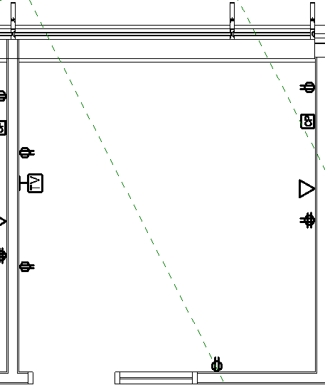
To start creating rooms or spaces, initiate the command from the ribbon, set the properties for the top, and click in the room or space where the tag should be placed.  Notice the cross-hairs and solid color fill pattern created. The cross-hairs indicate the center of any room/space tags should the "Tag All" be used.  This process gets repeated for every room, but for spaces it can be automated using the "Place Spaces Automatically" tool.  This uses the same settings for every space in one view. It also places the cross-hairs at the geometric center of the space, as desired for most spaces.  Be careful of L-shaped corridors and odd shaped spaces where the geometric center is located outside the space.  The tags will be outside the space too.  If there are a lot of spaces, then the project is likely large enough to have worksets enabled, which workset did you create the spaces on? Is it visible in all views? If not, neither are the tags.  If some of the spaces can't be seen, check the cut plain for the view range, if it is set higher than the room bounding ceiling, the space/room won't be visible in the view.

Should the space have sloped walls or a low sloped roof and knee wall configuration, then the "room computational height" setting will need to be checked per level (prior to 2012 it was a type parameter).  This will also come into play if there are sloped floors (think auditorium, parking garage, or classrooms with stadium seating).

The design process is not a static, and the dynamics of walls moving or deleting can wreak havoc on rooms and spaces.  Sure the balloon analogy is flexible, but for spaces the cross-hairs and geometric centers are not.  When a wall shifts far enough to encompass the cross-hair center point for the adjacent space, then there are redundant spaces and missing spaces.

So maybe there are some spaces that need deleting.  They can be deleted from the project from a plan view.  Should you desire to replace this space elsewhere in the project, it can be selected from the properties pull down during the space creation dialog.  To fully delete it from the project, a space or room schedule must be made.  It can be sorted and grouped  so all the ones saying "unplaced" are grouped together (by not selecting "Itemize every Instance" in the schedule sorting and grouping) and deleted at once.

Some rooms may need to be divided into smaller rooms without having a physical wall dividing them.

Room separation lines are used to accomplish this.  Please note these can be very problematic for Revit MEP users. The Room separation lines also divide spaces, even through a linked file.  They can't be simply turned off in visibility graphics, and they can't be put on a workset that isn't loaded (in both cases they still divide and are not visible).   This greatly complicates things for the MEP users.  There are some places where Room separation lines are completely necessary, but if possible try not to use them.
There are some other limitations on both rooms and spaces. Phasing works for rooms, but they must be created in each phase.  For those on subscription, there is an add-in to automate this process. Spaces don't work with phasing at all.  They also don't work with design options.  If the project is in 2013, no sweat, just tag the rooms through the link. If it's a previous release then a more creative solution will be needed.


Analysis

At the very least, rooms and spaces will be used to display room names and numbers.  Space tags in the MEP file should have the same name and number as the rooms in the architectural linked file. While this sounds simple enough, it can be surprisingly difficult to accomplish. Prior to the 2011 release, objects in a linked file could not be tagged period.  So Autodesk released a Room Name and Number synchronization add-on for Revit MEP.  Then in the 2011  release, objects could be tagged through a linked file, except for rooms. So the synchronization tool was still needed.  Another solution in both releases was to make a space tag that looked at the room parameters properties of spaces.  Finally in the 2012 release rooms can be tagged through a linked file.

Other then room names and numbers, space tags can be used to leverage our designs. Here are some suggestions: area, zone, watts/sqft, air changes per hour, average illumination, and any custom property imaginable.  For custom properties needing to be tagged, the property will need to be a shared parameter.  Don't let room names and numbers be the extents of how space tags get used.

Once rooms and spaces have been populated, they can also be used as leverage in schedules.
Room properties from a linked file can be included in schedules. When creating the schedule, make sure to select the pull down for "Select available fields from:" and make sure the "include elements in linked files" is checked. Or if the spaces are populated, they can be chosen too.  Since the models can be manipulated from the schedules or from the plan views, this makes for a good check or place to quickly adjust elements based off of where they are.

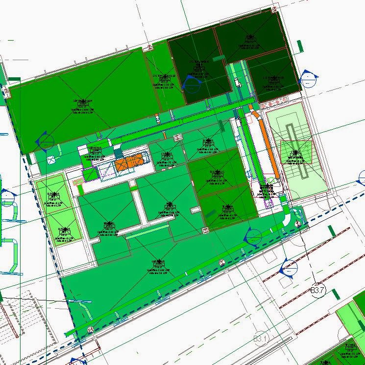
Another way we can use rooms and spaces to leverage our designs is to apply color schemes. Color schemes allows the user to dynamically see how changes to the design affect the results.  Here is an example of a lighting color scheme looking at the average estimated illumination value.  As lights are added or subtracted from a space, the color of the space changes.  

Color schemes can be set to show many useful values to improve the design process. In addition to the power values in the families placed in a space, the space itself has several properties for energy analysis each of which can have a color scheme.

HVAC CFM/SQFT
Electrical Watts/SQFT
Color schemes can be made up to display about any information needed to analyze a design. It is pretty neat to see it populate while working.  As of 2013 release there is a point in these families that extends down below to solve this problem.

Even more leverage can be gained by spending some time getting to know the energy analysis properties of spaces.  Most of these settings can be transferred via GBXML to other energy analysis programs greatly expediting your analysis.  What used to take a week or more can be done in hours.  Consult your re-seller about the specifics of which properties do and don't transfer to the various programs.  Some work much better than others.  GBXML also captures the building construction materials by the properties entered for the space information as space "Construction Types"
Unfortunately it does not pick up the actual types used in the architectural file, but a predefined list of construction types.  This list is customizable on a per computer basis, and not easily transferred.  The 2013 release does at least let the U values be overridden.  This limitation has been one of the biggest reasons we use external software for our load calculations and energy analysis.  Some other complications to be aware of with GBXML include:
Columns and column wraps, make them non-room bounding to prevent extra triangulation of surfaces.
Curved walls, again, extra triangulation is the problem. Try export with simple surfaces chosen.
Block walls w/ curtain walls above.  The block wall is thicker thus the area is smaller, and no surface is seen for the wall above, so it gets classified as an opening.

Rooms and spaces can greatly leverage our models to improve the design process. They do take some practice to implement and use effectively, but they are well worth the time spent.  If they are already being used to manage the room names and numbers, then the overhead of creating them is already being spent. Capitalize on the investment and find creative ways to use them to leverage all aspects of design, from scheduling to tagging to energy analysis.

Monday, August 11, 2014

Some Background on Backgrounds.

Managing file size in Revit must be a priority for large projects; else progress will slow to a painful pace. There are many places to manage, but for the MEP engineer, the first place to start is with the background files. The architect's files that are linked in as backgrounds are really just there for the floor plan, and model coordination. It would be fair to say that everything in the linked file is overhead for the performance of your model. So make it a minimal as possible. Delete as much out of it as you quickly can. Every byte of information you remove, saves time for each person opening the project. Delete out all of the sheets, every one of them. You're not linking to their sheets, so you're not using them. Delete them. Delete the schedules, the legends, the sections, and elevations too! If you're not linking to the view, delete it. Purge the heck out of it, till there is nothing left to purge. Obviously don't get too carried away. Make sure you don't really need something before you delete it. But the more you can delete, the better off everyone will be. The only things I usually keep in my background files are overall floor plans and RCP plans.


Don't invest too much time into this process. I have heard of people spending an hour or more deleting stuff out. Make it a quick process, where you get the most bang for your time. If you have the resources, write a script to delete stuff you know you won't use quickly. Get the process down to 5 minutes or less.  I usually get Architectural backgrounds starting around 125 megs, and can reduce it to about 54 megs.  Your mileage may vary.

Thursday, August 7, 2014

Retooling the Revolution

Retooling is often a phrase we here for factories getting an upgrade to make a new model of widget, or as an upgrade to help them produce the widgets faster.  I believe the AEC industry is in the midst of retooling for the Digital Design Revolution.  Why you may ask? BIM is producing more data then we know what to do with.  We need to become better at sorting though all this data to make educated informed decisions, without drowning. We need to learn to swim though the sea of data.

The AEC industry for ages has revolved around the all mighty drawing set.  The printed (or hand drawn) set of documents that communicated to the construction trades the extents and quality expectations of their work.  This is no longer the case.  The drawing set is being replaced by digital models.  Digital models heaping with data.  We need the ability to sort though the data, gather specific bits of it to make decisions.  The authoring software usually does a pretty good job of helping us do that, when it falls short, when we need a specific task not built into it, that is when we start to drown.  This is where we need to retool.  Accessing and manipulating databases is what we don't have the skills and tools to handle. Sure many of us learned how to script for AutoCAD,  or maybe to write a macro in excel, but how many of us have learned to write a macro for Revit, or an add-in even.  How many of us have learned how perform a query on an SQL database or to link it to real objects in the Revit database? Do we need to become proficient programmers in C#, Python, Ruby on Rails, or the next hot programming language?

This is the kind of retooling I am proposing.  I don't believe we need to all become programmers before we become designers and engineers, but these are the tools of this generation.  These are the tools that will differentiate us from the competition.  Perhaps we will hire a programmer on staff, perhaps keep one on retainer like a lawyer. No matter the arrangement, programming and data management needs to be part of the tool kit for the BIM world.

Saturday, July 26, 2014

Use Excel with Revit!!!

I know what you're thinking, Revit does not support importing and exporting of data with Excel. Your right, natively it does not.  So right off the bat we need to talk about add-ins.  There are several out now that you can buy to allow you to create and sync data with Excel.


And I'm sure there are more. Each has its pros and cons.  My personal favorite is Rushforth Tools.  The cost is very reasonable, and you get so much more then just the ability to use Excel.  Personally I wouldn't use Revit without it.  

Now there are some things to know before you start manipulating data with Excel, and pushing it back into your model. For starters, every single little object in a Revit model has a unique element ID, and I mean everything. Most of the add-ins will by default create a column identifying this property. Don't mess with it, ever. There really shouldn't be a need to, but it would really confuse the software for these values to change. It is a very good property to use for keeping track of things as it does not change. 

Next, what kinds of stuff might you want to change?  The limits are almost boundless here and will likely be an entire post itself in the future. Some brief suggestions, how about shared parameters used for scheduling, or coordinating your ceiling heights with the heights of ceiling devices, or pushing CFM values from your load calculation software into the spaces, and then to the devices in those spaces. I could go on, but that's just a sampling.  What kinds of data would you like to sync with Excel?  Do you have any favorites you are already using? Leave a comment and let's discuss.

Wednesday, July 23, 2014

Family Annotation Symbols

Annotation Symbols are used to represent an object that would not be well represented otherwise.  A classic example is an electrical duplex receptacle. If you were to accurately draw from plan view what would be seen at 1/8" scale and account for a thick line weight, you might notice a slight budge on the wall from the face plate. You would have no idea what it meant if noticed at all.  Let's introduce a circle with two off center lines and we can see where and what should be along the wall.


This symbol does not change size with a change in scale. This is correct. The size after all was somewhat arbitrary to begin with. Wait a minute, you changed scales from 1/8" to 1/2" on your view and the symbols got much smaller?


Yes, they should have.  The scale is larger, but the printed size is the same, so in your view it looks smaller, because your view is larger.  Put it on a sheet, and overlay it to the same space at 1/8" scale and the annotation symbol will be exactly the same.

Sometimes multiple devices need to be shown at the same location. Think about a fire alarm plan showing a pull station and a horn strobe (typically above). How though do we keep the model accurate, drawings legible and not have devices violating the laws of physics, by utilizing Robert Bell's technique for shifting


The switches in the picture above are too tight together in reality. If we showed them true to scale, the annotation symbols end up on top of one another and we can't read the drawings. Using Robert's technique, we can shift the symbol to be legible without shifting the physical switch. I didn't cheat I promise. Notice the blue switch symbol has a drag arrow at the bottom of it. That is the trick.

This gets potentially more complicated with multiple scales. Yes it is a lot of work to build, but it will be used much more then you might expect. It is certainly worth it. I find it useful for switches, power outlets, data outlets, and Fire Alarm devices all the time. Do you have any suggestions for using this technique for Plumbing, or HVAC?

.

Tuesday, July 22, 2014

Tuesday, July 8, 2014

Who gets paid for coordination?

Generally speaking, the engineer is responsible for designing a system that can fit in the space provided.  Coordination is the responsibility of the General Contractor (GC).  You don't believe me? Check your contract. There will be about a 15% allotment for coordination given to the GC. Who is responsible for submitting coordination drawings to be approved? The GC. It is the engineer who is responsible to review and approve or reject them. These tables seem to have been flipped with the introduction of BIM.  On every single BIM job I have worked on, the GC has complained about not being provided a "fully" coordinated model.   Upon investigating further, the clashes were often minor and insignificant. Things I would expect to be resolved through the coordination drawing review process.  Further more, these models are much more coordinated then any of the 2D cad projects we have produced in the last 20+ years.  Why were there not the same complaints then? I believe this is an excuse for the GC to get more time and to reduce their cost of coordination.  Can or should that 15% fee be moved over to the engineer?  We are doing the work anyway.  Then would we be agreeable to taking on the increase in liability that comes with coordination? Some would say that we already are when we approve the coordination drawings. How should this contractual arrangement be revised?  There seems to be an expectation by the owner and GC that if Revit is used on a project by the design team, the model must be perfectly coordinated by the design team?


Sunday, July 6, 2014

Coming of the 2nd AEC Digital Revolution

The world of Architecture, Engineering and Construction (AEC) is going through a second digital revolution.  The first was when computers and CAD replaced the pencil and drafting table.  Now as the computing age has evolved, the AEC industry is going through a second digital revolution.  The goals of the first were to replace the tedious process of drafting with one that was faster, more consistent  and easily editable.  The new revolution goes well beyond these goals.  We are no longer just trying to mimic hand drafting with the computer, but to build a virtual 3D model of every element used in assembling the building. It has been dubbed Building Information Modeling (BIM). The goal of BIM is to generate data to be used for collaboration, coordination, scheduling, cost estimating and many more.  It is generating much more data then the AEC industry has ever had access to.  This creates whole new challenges and opportunities. John Naisbitt coined the phrase "we are drowning in information, but we are starved for knowledge". in his 1982 book Megatrends.  Here lies the focus and purpose of this blog, to learn to swim in this sea of data in this second Digital Design Revolution.