Saturday, July 26, 2014

Use Excel with Revit!!!

I know what you're thinking, Revit does not support importing and exporting of data with Excel. Your right, natively it does not.  So right off the bat we need to talk about add-ins.  There are several out now that you can buy to allow you to create and sync data with Excel.


And I'm sure there are more. Each has its pros and cons.  My personal favorite is Rushforth Tools.  The cost is very reasonable, and you get so much more then just the ability to use Excel.  Personally I wouldn't use Revit without it.  

Now there are some things to know before you start manipulating data with Excel, and pushing it back into your model. For starters, every single little object in a Revit model has a unique element ID, and I mean everything. Most of the add-ins will by default create a column identifying this property. Don't mess with it, ever. There really shouldn't be a need to, but it would really confuse the software for these values to change. It is a very good property to use for keeping track of things as it does not change. 

Next, what kinds of stuff might you want to change?  The limits are almost boundless here and will likely be an entire post itself in the future. Some brief suggestions, how about shared parameters used for scheduling, or coordinating your ceiling heights with the heights of ceiling devices, or pushing CFM values from your load calculation software into the spaces, and then to the devices in those spaces. I could go on, but that's just a sampling.  What kinds of data would you like to sync with Excel?  Do you have any favorites you are already using? Leave a comment and let's discuss.

Wednesday, July 23, 2014

Family Annotation Symbols

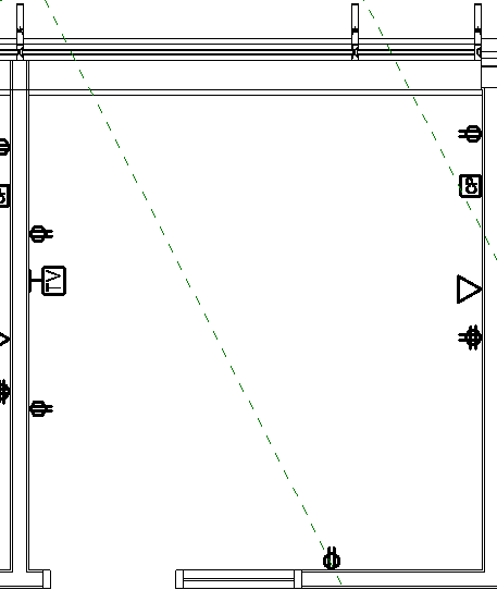
Annotation Symbols are used to represent an object that would not be well represented otherwise.  A classic example is an electrical duplex receptacle. If you were to accurately draw from plan view what would be seen at 1/8" scale and account for a thick line weight, you might notice a slight budge on the wall from the face plate. You would have no idea what it meant if noticed at all.  Let's introduce a circle with two off center lines and we can see where and what should be along the wall.


This symbol does not change size with a change in scale. This is correct. The size after all was somewhat arbitrary to begin with. Wait a minute, you changed scales from 1/8" to 1/2" on your view and the symbols got much smaller?


Yes, they should have.  The scale is larger, but the printed size is the same, so in your view it looks smaller, because your view is larger.  Put it on a sheet, and overlay it to the same space at 1/8" scale and the annotation symbol will be exactly the same.

Sometimes multiple devices need to be shown at the same location. Think about a fire alarm plan showing a pull station and a horn strobe (typically above). How though do we keep the model accurate, drawings legible and not have devices violating the laws of physics, by utilizing Robert Bell's technique for shifting


The switches in the picture above are too tight together in reality. If we showed them true to scale, the annotation symbols end up on top of one another and we can't read the drawings. Using Robert's technique, we can shift the symbol to be legible without shifting the physical switch. I didn't cheat I promise. Notice the blue switch symbol has a drag arrow at the bottom of it. That is the trick.

This gets potentially more complicated with multiple scales. Yes it is a lot of work to build, but it will be used much more then you might expect. It is certainly worth it. I find it useful for switches, power outlets, data outlets, and Fire Alarm devices all the time. Do you have any suggestions for using this technique for Plumbing, or HVAC?

.

Tuesday, July 22, 2014

Tuesday, July 8, 2014

Who gets paid for coordination?

Generally speaking, the engineer is responsible for designing a system that can fit in the space provided.  Coordination is the responsibility of the General Contractor (GC).  You don't believe me? Check your contract. There will be about a 15% allotment for coordination given to the GC. Who is responsible for submitting coordination drawings to be approved? The GC. It is the engineer who is responsible to review and approve or reject them. These tables seem to have been flipped with the introduction of BIM.  On every single BIM job I have worked on, the GC has complained about not being provided a "fully" coordinated model.   Upon investigating further, the clashes were often minor and insignificant. Things I would expect to be resolved through the coordination drawing review process.  Further more, these models are much more coordinated then any of the 2D cad projects we have produced in the last 20+ years.  Why were there not the same complaints then? I believe this is an excuse for the GC to get more time and to reduce their cost of coordination.  Can or should that 15% fee be moved over to the engineer?  We are doing the work anyway.  Then would we be agreeable to taking on the increase in liability that comes with coordination? Some would say that we already are when we approve the coordination drawings. How should this contractual arrangement be revised?  There seems to be an expectation by the owner and GC that if Revit is used on a project by the design team, the model must be perfectly coordinated by the design team?


Sunday, July 6, 2014

Coming of the 2nd AEC Digital Revolution

The world of Architecture, Engineering and Construction (AEC) is going through a second digital revolution.  The first was when computers and CAD replaced the pencil and drafting table.  Now as the computing age has evolved, the AEC industry is going through a second digital revolution.  The goals of the first were to replace the tedious process of drafting with one that was faster, more consistent  and easily editable.  The new revolution goes well beyond these goals.  We are no longer just trying to mimic hand drafting with the computer, but to build a virtual 3D model of every element used in assembling the building. It has been dubbed Building Information Modeling (BIM). The goal of BIM is to generate data to be used for collaboration, coordination, scheduling, cost estimating and many more.  It is generating much more data then the AEC industry has ever had access to.  This creates whole new challenges and opportunities. John Naisbitt coined the phrase "we are drowning in information, but we are starved for knowledge". in his 1982 book Megatrends.  Here lies the focus and purpose of this blog, to learn to swim in this sea of data in this second Digital Design Revolution.